High-Speed Vision Solution for IC Chip Marking Inspection and Recognition
Real-time, reliable inspection tailored to surface, scale, and speed
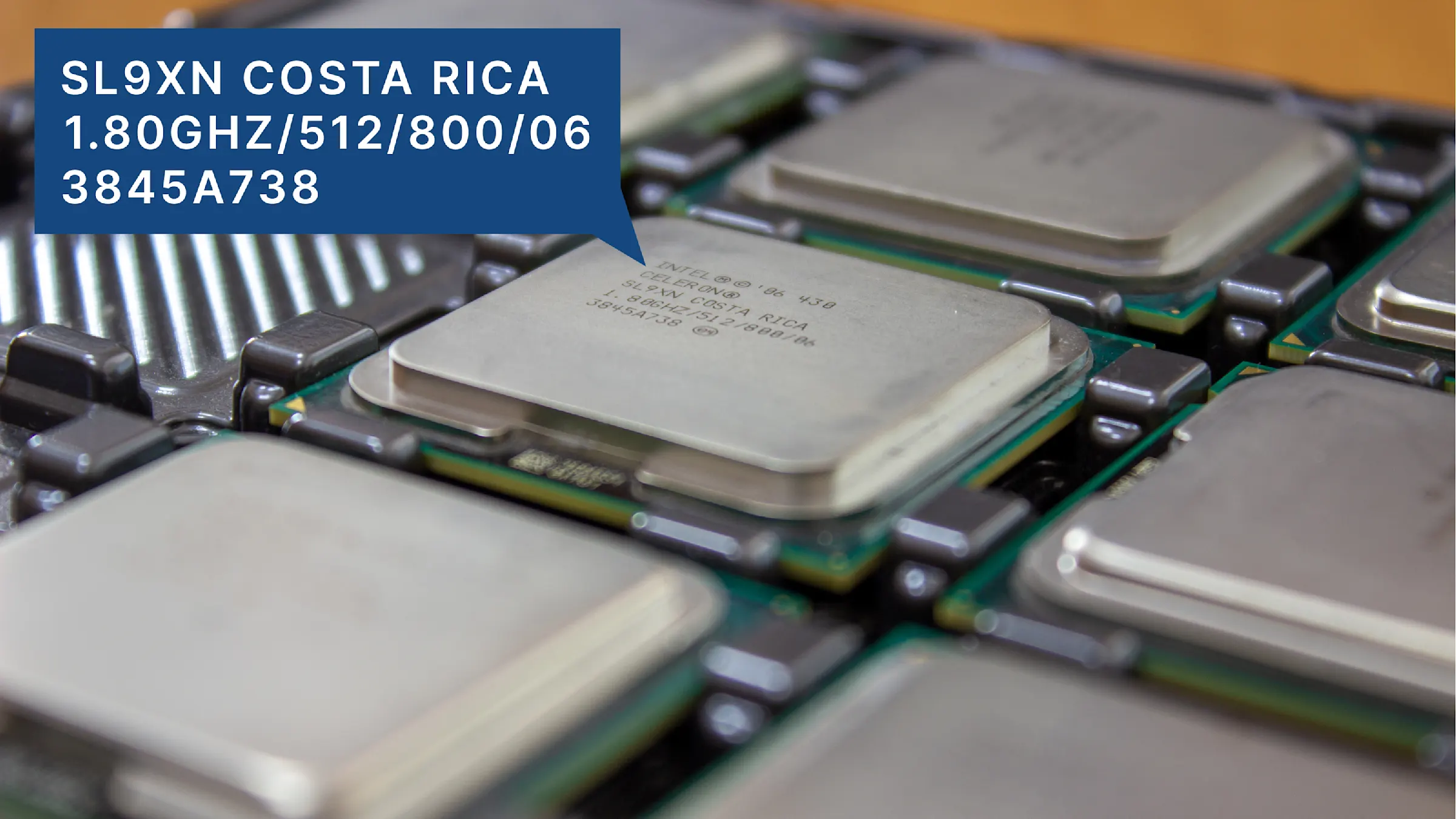
In semiconductor IC production, surface marking inspection and recognition are vital for traceability, quality control, and anti-counterfeiting. Engineers rely on these markings for yield feedback and quality improvement across suppliers and production batches. This page outlines key vision inspection challenges and how they’re addressed in practice—based on insights from multiple real-world implementations.

Solving complexity in marking validation workflows
In semiconductor back-end processes, IC chips undergo a series of marking validation steps—positioning, surface quality inspection, and recognition—before final assembly. These tasks, while standard in theory, pose real-world machine vision challenges due to material diversity, mark inconsistencies, and speed demands.

1. Positioning checks
Key challenges:
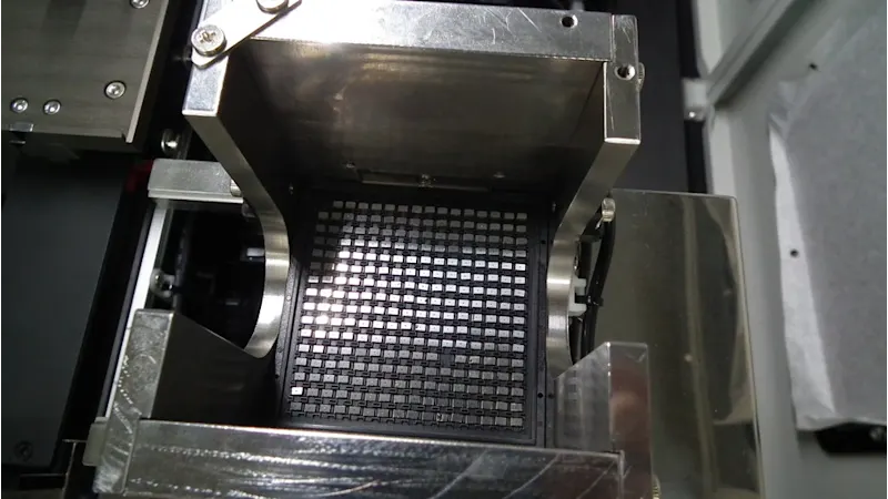
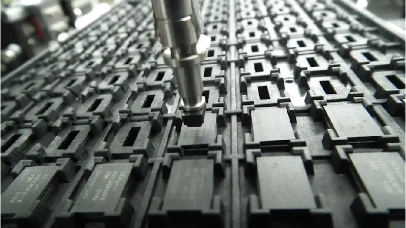
High-density trays and miniaturized packages make it difficult to detect chip misalignment or duplication.
Achieving sufficient resolution across a wide Fiield-of-View (FoV) requires balancing pixel density and sensor size.
In high-speed systems, sub-frame-level synchronization between image acquisition, lighting, and processing is required.
Common practice:
Use area scan imaging for static trays, stepping across multiple FoVs to cover the entire array.
Switch to line scan imaging for continuous or belt-based setups to acquire high-resolution images with minimal mechanical complexity.
Binary filtering is applied as a first-pass detection method.
Practical implementation tips:
Area scan and line scan imaging each have their respective advantages and must be evaluated based on project needs. In the processing stage, geometry validation and grayscale ROI analysis help achieve production-level reliability by uncovering subtle misalignments and duplicates.

2. Surface and marking quality check
Key challenges:
Marking contrast varies significantly across materials:
Epoxy can have textured or uneven surfaces
Ceramic often causes specular glare
Metallic caps reflect light unpredictably and cause saturation
Uniform lighting rarely performs consistently across mixed-material lots
Non-uniform marks (burned, shallow, or partially obscured) are difficult to quantify using fixed thresholds
Common practice:
Coaxial lighting is commonly used on polished or reflective parts
Low-angle dark-field lighting enhances texture-based contrast on matte surfaces
HDR imaging is applied to suppress saturation and boost weak signal areas
Practical implementation tips:
Understanding the problem requirements is step one, but effective development still hinges on matching theory with actual material behavior. It's important to test lighting geometry, wavelength, diffuser configuration, and gain settings across actual samples to achieve contrast stability across trays. Telecentric lenses, for instance, eliminate perspective distortion but may limit flexibility if working distance isn’t precisely defined.

3. Recognition of alphanumeric, codes, and symbols
Key challenges:
Similar-looking characters (e.g., 0 vs. O), inconsistent spacing, or broken strokes cause reading confusion
Fonts become distorted during marking due to warpage or focus issues
Readable marks may still fail due to poor segmentation or low confidence scores
Common practice:
Template-based OCR engines are used for known fonts and predictable layouts
Symbol filters or rule-based validation (e.g., expected format) are added for robustness
Practical implementation tips:
Deep learning-based OCR models can reconstruct likely character shapes even when strokes are incomplete or distorted. Decision points like model selection, adapting the OCR pipeline to real application conditions, and defining how much marking variability the model should tolerate all impact the results and need to be considered from a systems approach.
Beyond standard specs — vision integration that performes in production
Most machine builders know what they want—HDR imaging, autofocus, coaxial lighting, deep learning OCR—but where systems succeed or fail is in how these elements are implemented under real production constraints.
It’s not just about selecting hardware; it’s about integrating it to perform consistently across diverse materials, tray layouts, and inspection conditions. From optical stack optimization to acquisition strategy and vision logic, we help reduce integration overhead and accelerate reliable deployment. For example:
Lighting geometry, gain curves, and trigger timing are tuned against real sample sets to maintain inspection stability.
We help navigate design trade-offs—balancing FoV vs. resolution, contrast vs. exposure tolerance, distortion handling vs. working distance flexibility.
Where needed, we embed HDR and lighting control at the camera level, avoiding downstream programming overhead.
These aren't off-the-shelf decisions. They’re system-level trade-offs across optics, acquisition, and logic—ensuring a setup that not only looks good in spec sheets, but holds up under throughput and variation on the factory floor.
Discuss your project with usWe’ve encountered cases where the customer initially believed the issue was with software or image processing—but it ultimately came down to the optical setup. A few key adjustments to lighting angle, lens selection, and even camera housing design made the entire system perform beyond expectations.
From proof of concept to production—faster
Standard vision components alone won’t close the gap between lab success and factory reliability. Real-world marking validation demands more: consistent imaging under material variation, reliable logic under speed constraints, and easy maintainability across product changeovers.
That’s why we prioritize fast, tailored proof-of-concept—built around your samples, layouts, and throughput goals. We don’t just demo features; we validate feasibility and provide integration insights that reduce your engineering load.