Trigger Boards
Synchronize your image processing system
Synchronous image and signal processing: trigger boards control the frame grabber's image acquisition, camera triggering, and external peripherals.
Frame grabber trigger boards control image and signal processing
To control image acquisition and synchronize the hardware peripherals of an image processing system (such as cameras, lighting, light barriers, shaft encoders, etc.) in real time, frame grabbers offer powerful signal processing in addition to image processing. Trigger boards control the frame grabber’s image acquisition process and the camera's exposure times by handling general purpose input/output (GPIO) data signals. Our boards were developed in our Mannheim branch (formerly Silicon Software) to perfectly support our frame grabbers' functionality.
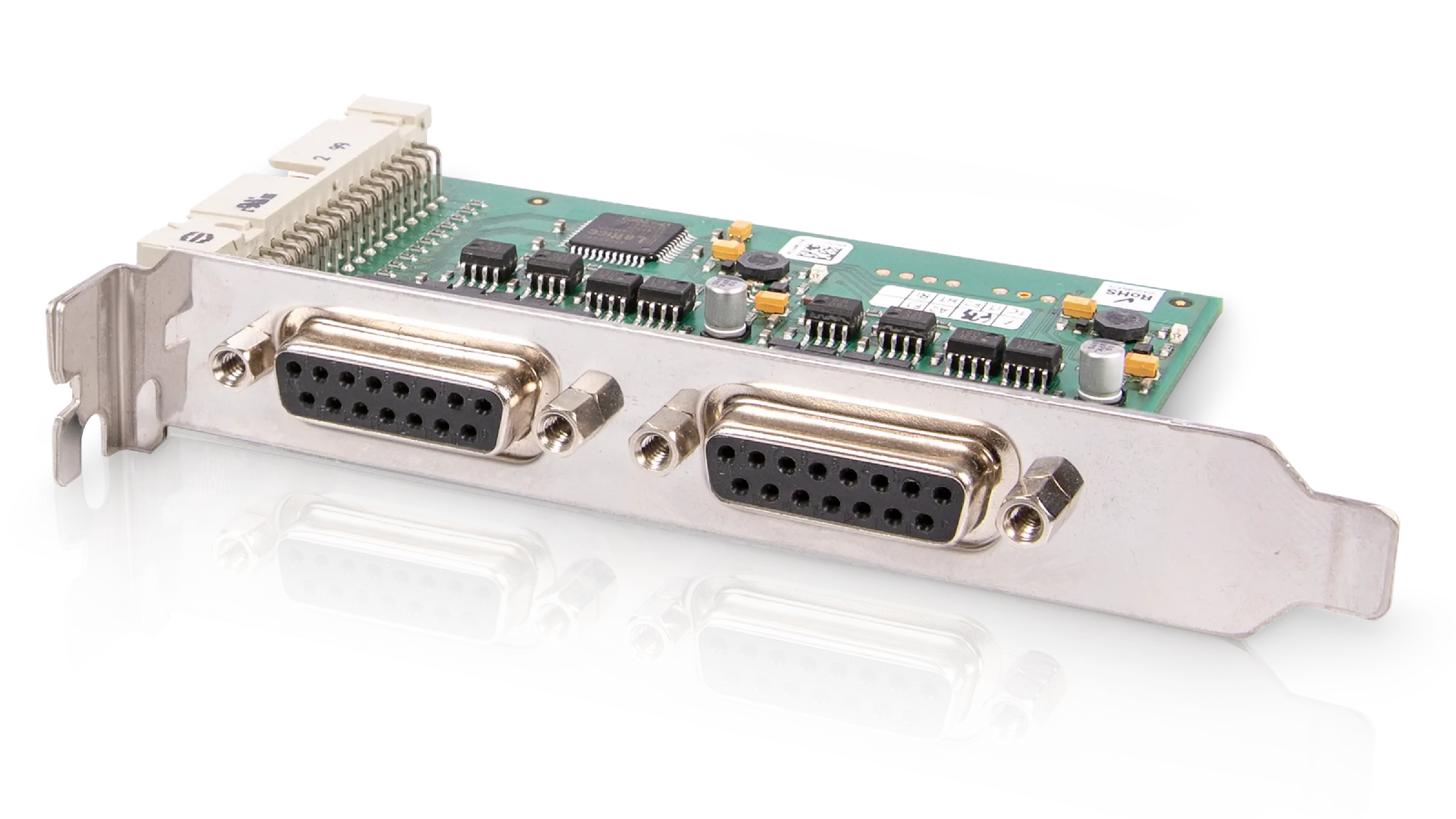
Trigger boards are plugged into the connector located on our frame grabbers via a 34-pin flat ribbon cable. The cable is available in various designs, including left, right, and customer-specific options for multi-device connections.
Overview: Trigger boards synchronize the image processing system
Select from various physical GPIO options, such as TTL and opto-coupled signals. A trigger board is available for each option: the TTL trigger enables an adjustment to the TTL signal level; the opto-trigger allows galvanic isolation and an adjustment to the industrial signal level (typically 5 to 24V).

Opto trigger: opto-coupled signals
TTL trigger: standard TTL level
Multiple input and output signals (max. 8x in, 8x out)
Synchronize the image acquisition process
Synchronize multiple cameras in the image acquisition process
Camera exposure time control
Independent control of multiple cameras connected to a frame grabber
Highly flexible graphical programming of user-defined trigger functions with VisualApplets


