Quality Control in Electrode Coating
Machine vision detects particles and voids with large amounts of data
Coating the substrate foil with slurry is a critical production step. The surface quality must be uniform, free of voids and particles, and the thickness of the slurry must be precise and homogeneous. Our vision technology handles the high speed of this process step, helping to significantly reduce material waste through accurate analysis.
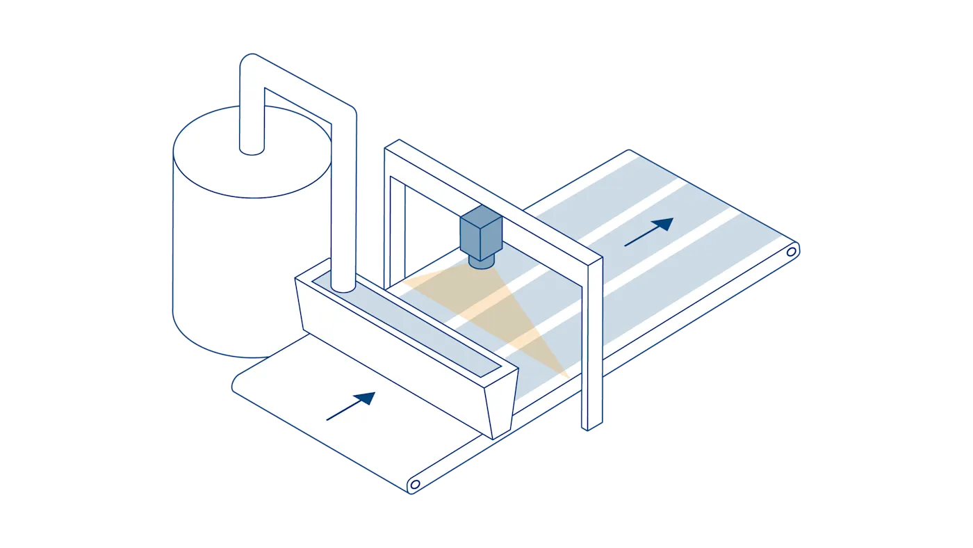
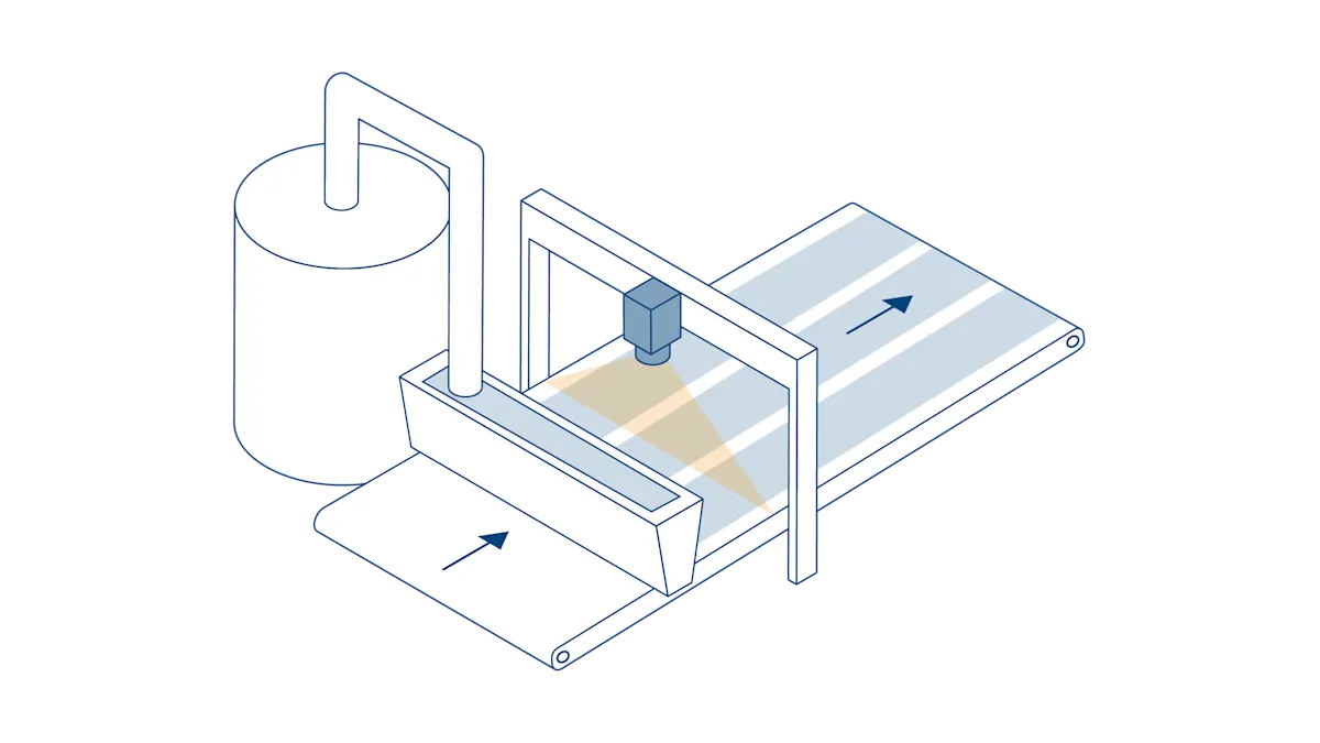
Electrode coating in detail
In electrode coating, the carrier or substrate foil is coated with the previously mixed slurry using an application tool such as a slot die, doctor blade, or anilox roller. The top and bottom sides of the foil can be coated in parallel or sequentially. This is followed by a drying process.
A correctly applied electrode layer has a decisive influence on battery performance
This process step is particularly critical because many parameters must be precisely coordinated: the slurry must have the required stability and be applied at the correct rate. The aim is to achieve perfect coating homogeneity, without cracks or agglomerates, as the electrode layer is particularly important for battery performance.

Possible defects in slurry application
Defects can occur in both intermittent and continuous electrode coating. They depend on the viscosity of the slurry and the accuracy of the dispenser.
Typical defects are:
a. Agglomerate
b. Coating crack
c. Contamination
d. Micro-compression
e. Mud crack
f. Pinhole
g. Slip
h. Stripe
The challenge of large image data
Production speeds of up to 80 m/min and high detail accuracy
Image processing during production presents a dual challenge: very high production speeds, which generate large amounts of image data. At the same time, a high level of detail is required (which is achieved through high image resolution), generating even larger amounts of data. Conventional solutions generally do not have the processing power required to maintain the required production speeds.
Our vision technology ensures reliable quality control in electrode coating

Only a fraction of the data needs to be analyzed thanks to image pre-processing
The highly-sensitive line scan cameras in our racer and racer 2 series are designed for web material. They deliver the required throughput and image quality for this demanding application. By combining the Basler VisualApplets software and a frame grabber, image data is pre-processed, creating the necessary focus for further image processing. By determining the region of interest (ROI), only the areas with irregularities are localized for inspection—meaning only the image data from the ROI is processed. This allows the CPU of the IPC to continue to be used for the actual system control without any additional load.

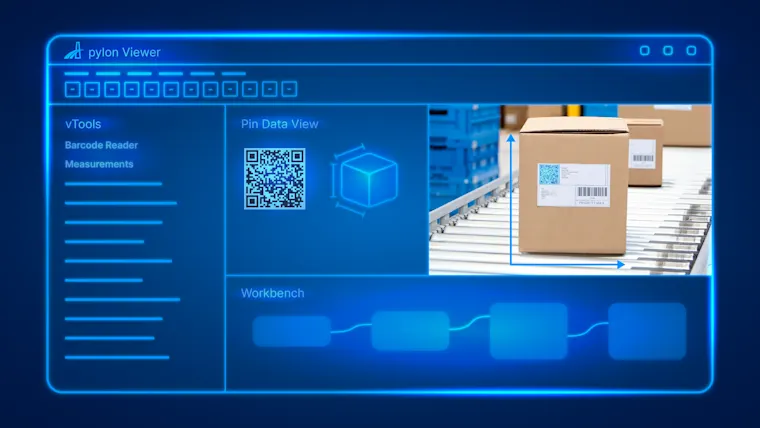
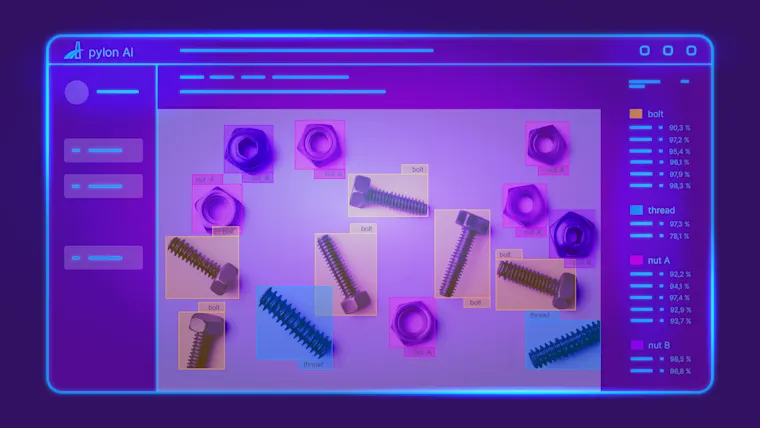
Classify defects and make qualified decisions with pylon vTools
In the next step, irregularities within the ROI can be further analyzed. You have the choice between Basler pylon vTools with classic algorithms or pylon AI vTools with AI algorithms in order to
classify the type of defect or
measure the size of the defect.
Depending on the type and size of the defect, a decision is made as to whether it falls within tolerances or whether further measures are required. Defective areas can be precisely removed thanks to exact localization and measurement. This improves the quality of the battery cell and minimizes material waste.
Products for this solution
Looking to implement a comparable solution? These products will help you.