Machine Vision for Flux Jetting, Indium TIM, and Heat Spreader Assembly in FCBGA
Demand for high-performance semiconductor packages for AI, HPC, and automotive applications is increasing thermal management requirements. Indium-based Thermal Interface Materials (TIMs) are increasingly used to improve heat transfer from the die to the heat spreader. Meanwhile, larger packages, evolving TIM materials, and emerging fluxless processes are changing assembly and vision requirements.
This article explores these changes from a machine vision perspective and what they mean for next-generation Indium TIM assembly equipment.

What is changing for Indium TIM assembly equipment?
For high-power FCBGA packages, Indium and InAg TIMs are already being used to form the thermal interface between the die and heat spreader. Today, flux-assisted Indium TIM assembly introduces vision requirements for flux jetting inspection, Indium preform alignment and placement verification, and heat spreader alignment.
For the vision system design, the main developments are:
Larger package formats require larger field of view (FOV) without compromising placement performance.
Different optical targets range from low-contrast flux to reflective Indium and metal heat spreaders.
Z variation and package warpage can affect focus and measurement stability.
Looking ahead, fluxless Indium TIM processes could change both the assembly and inspection sequence. Flux application and inspection may be removed, while alternative oxide-control methods are introduced. Indium placement and heat-spreader alignment remain important process steps.
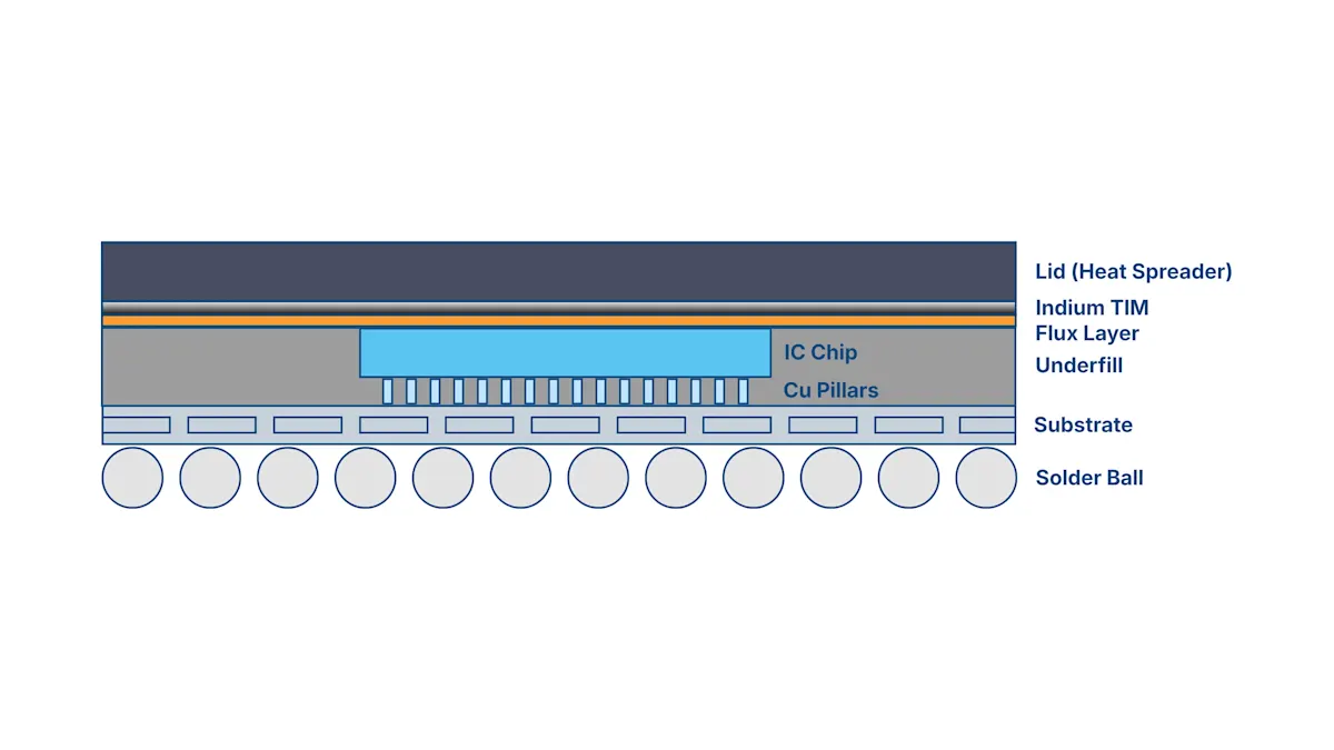
Where vision supports Metal TIM assembly?
In a flux-assisted process, vision supports several steps before the thermal interface is finally enclosed. Each step presents a different optical target. Low-contrast flux, reflective Indium preforms, and a much larger lid place different requirements on contrast, FOV, and positioning.
Flux jetting inspection
Imaging requirement
Thin, transparent flux provides limited contrast against the underlying surface. The vision system must reliably verify flux presence and application consistency across the die or wafer surface.

System design
High-resolution area scan imaging for flux inspection
Controlled illumination to establish sufficient flux-to-background contrast
Compact, single-cable camera configurations can simplify machine integration
Application considerations
Select resolution based on the required FOV and detectable flux feature
Image enhancement may be required where non-uniformity affects inspection consistency
Consider height or warpage compensation where Z variation affects imaging
Unlock article "Machine vision for flux jetting, indium Tim, and heat spreader assembly in FCBGA" for free
Unlock the full article "Machine vision for flux jetting, indium Tim, and heat spreader assembly in FCBGA". Sign in to My Basler or use the form – free and non-binding.