Cameras for Fluorescence Microscopy OEM
What camera features matter most for fluorescence microscopy?
Fluorescence microscopy requires cameras that can detect very low light levels with high accuracy for a broad range of life science and medical applications. Key factors include high sensitivity, low noise, and a wide dynamic range to capture faint fluorescence signals clearly. When you choose a camera for fluorescence microscopy, it is important to find a balance between certain sensor properties, camera-related aspects, and the needs of the intended applications.
Last updated: 07/14/2023
Reading time: approx. 13 Minutes
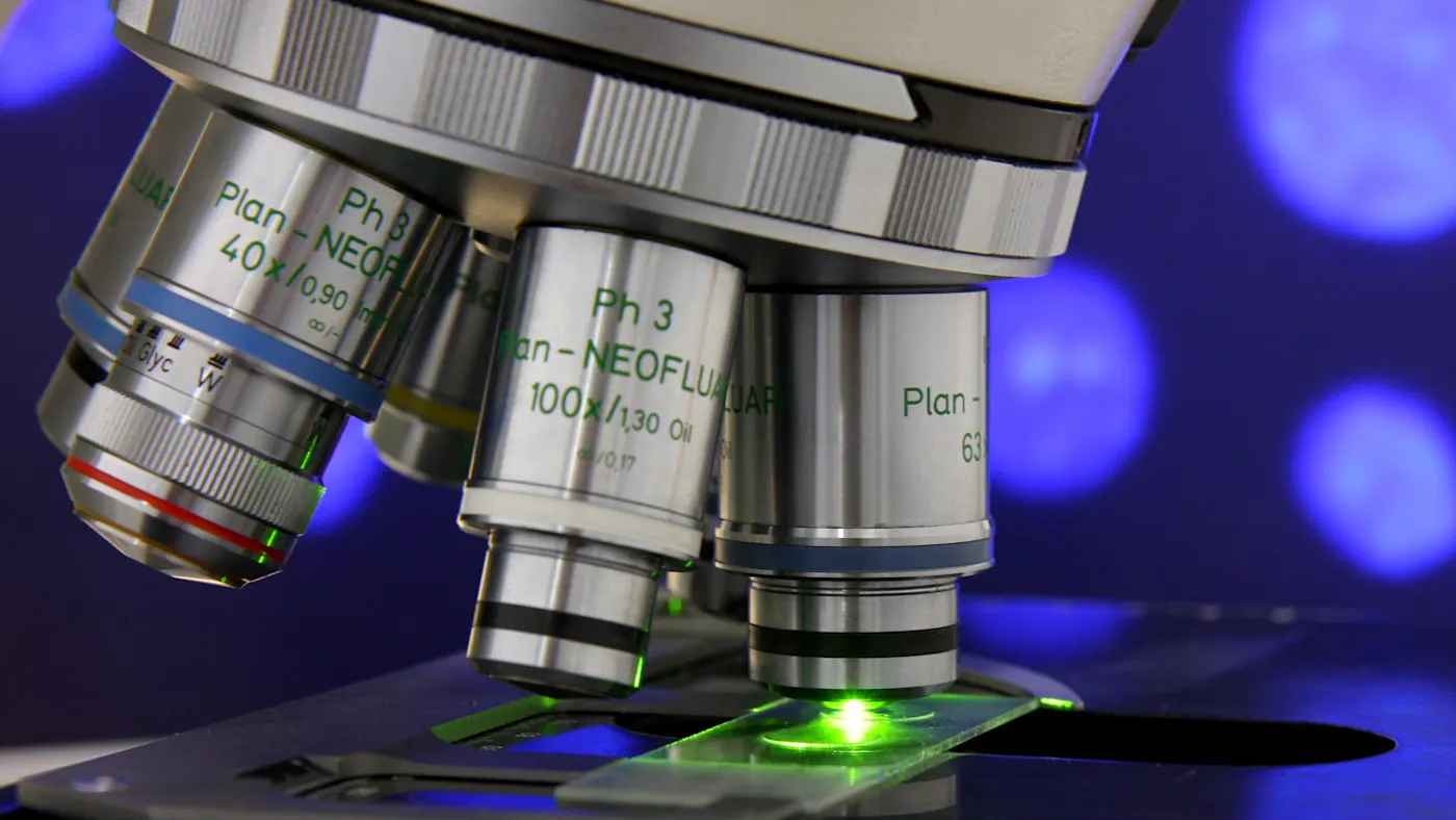
CMOS sensors in fluorescence-based applications
In many systems, such as those used for medical, life science research, or clinical diagnostic applications involving fluorescence-based methods, CCD sensors need to be replaced by CMOS sensors to capture higher-quality images with higher frame rates and less noise. This white paper provides information on selecting the best camera for your specific application, keeping in mind any technical considerations.
Learn how CMOS sensors enhance fluorescence imagingWhy optical format and resolution matter
When you look at the visible wavelength range, the optical setup does not differ significantly from normal light microscopy applications in terms of format, magnification, and resolution. However, the overall cost can increase when larger optical formats, such as F-mounts, are used.
Key optical formats include:
CCD vs CMOS sensors
For a long time, CCD sensors were the established technology in the market for fluorescence microscopes. This has changed in recent years, even if they are still available on high-quality microscopy cameras. CMOS technology has become increasingly prevalent and a competitive advantage in recent years.
Noise levels are now comparable to or even better than those of traditional CCD sensors. At the same time, the newer technology enables higher speeds, higher resolutions, and lower power consumption/heat dissipation, all at lower prices.
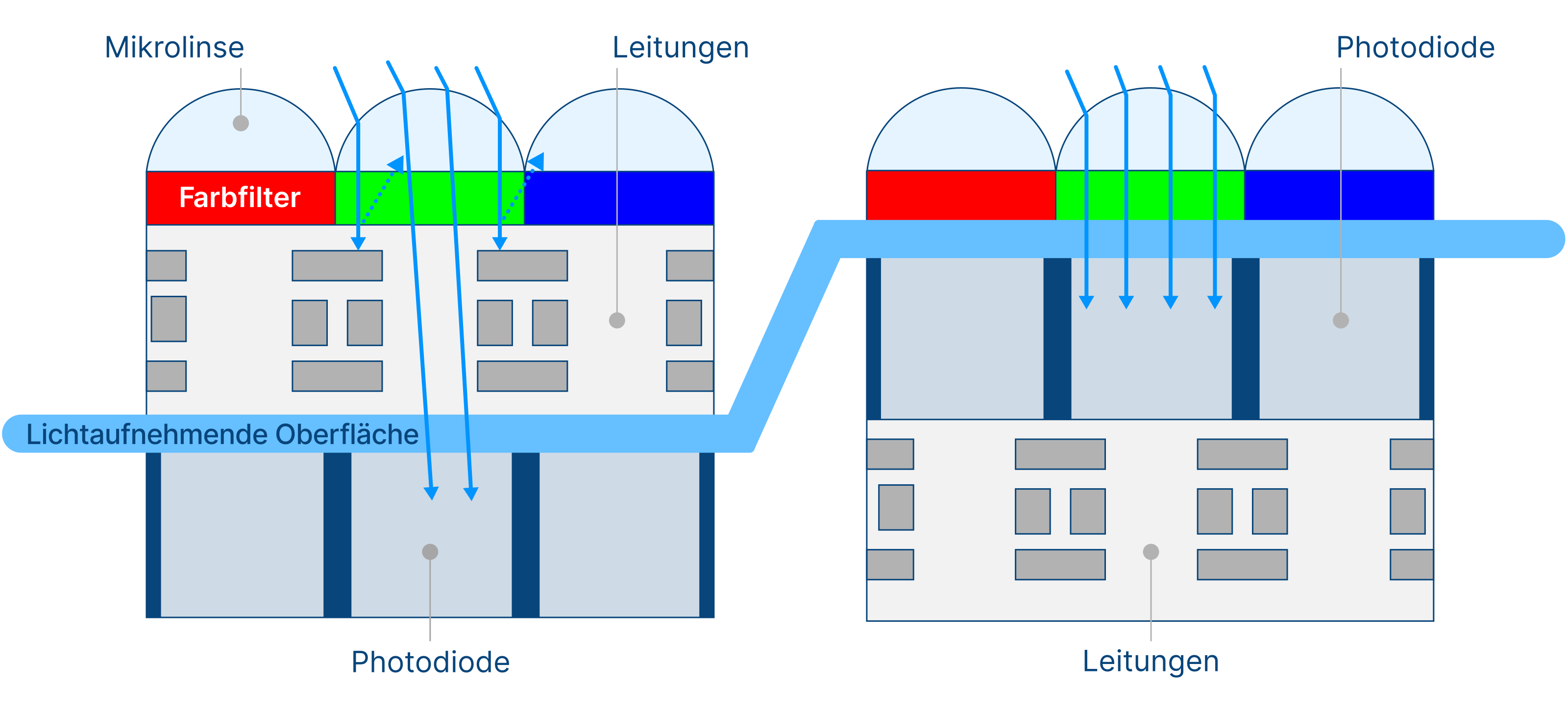
CMOS sensors are still developing rapidly. For example, Backside Illumination (BSI), an advanced imaging technique in industrial sensors, creates an inversion of the pixel structure to present the light-sensitive photodiode directly under the micro-lenses, which significantly increases the quantum efficiency of the pixels.
Monochrome vs color cameras
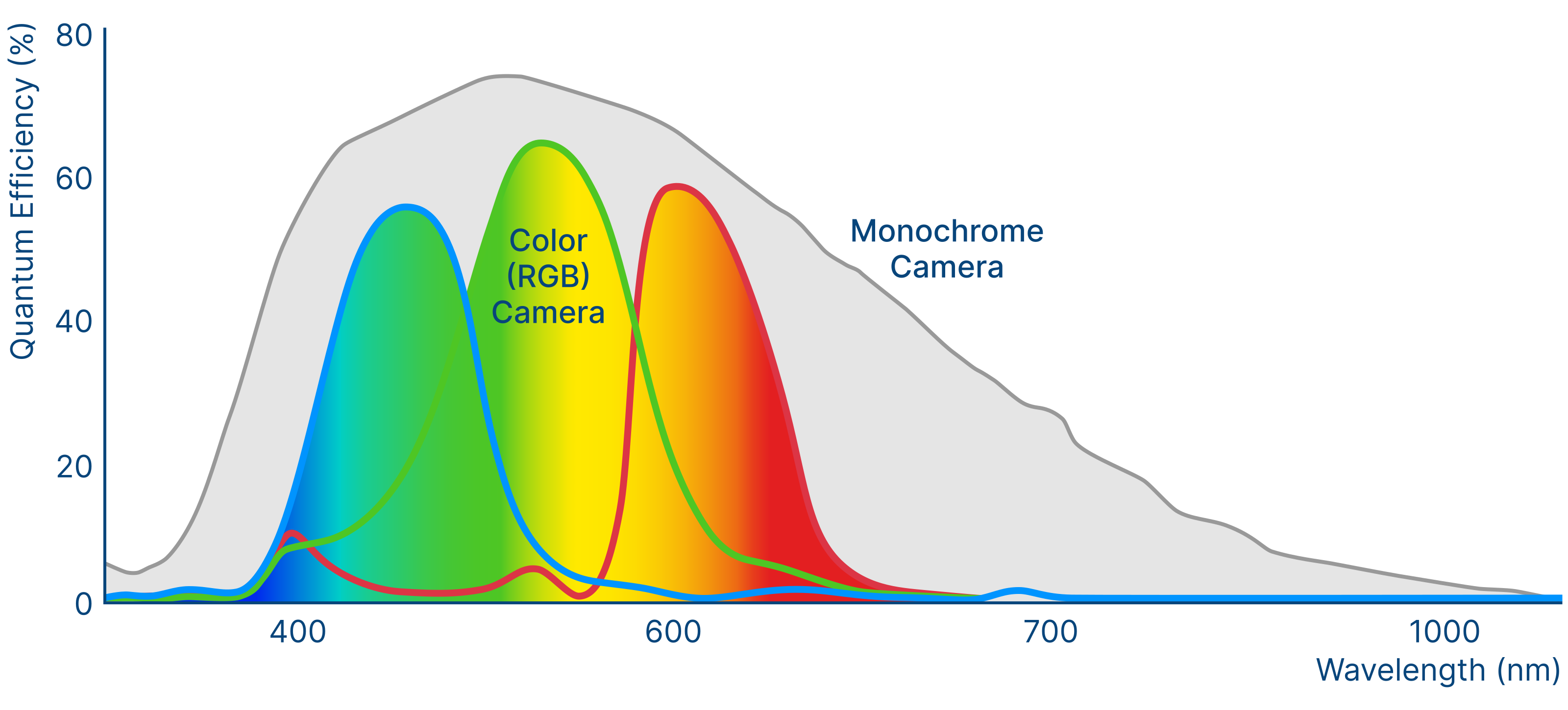
Generally, monochrome cameras are preferred for fluorescence applications due to their higher quantum efficiency. This is because color cameras have Bayer microfilters on each pixel that let only certain wavelengths pass through. Filtering is needed to calculate the image’s color information using a process called debayering. As the color filters block a certain amount of light, fewer photons reach the photon-reactive area of the pixel. In addition to the Bayer pattern on the sensors, the IR-cut filter in color cameras presents a limiting factor because it blocks light of approximately 650 to 700 nm upward.
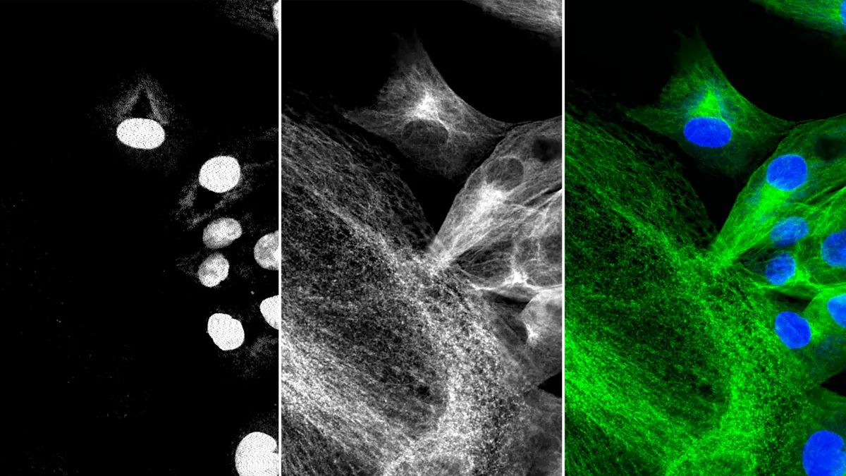
Typically, images with multiple fluorescence markers for specific detection and co-localization of molecules of interest are made from separate images using monochrome cameras. Selectable light sources and filter sets provide the right combination of excitation and emission wavelengths for each fluorophore used.
However, certain applications may create a demand to do color imaging and fluorescence within one instrument using only one camera. This is possible if the sensitivity demands of the fluorescence application are not too high.
Basler provides both monochrome and color cameras, tailored to your microscopy imaging application.
Explore both camera options with our teamHow global and rolling shutter affect fluorescence imaging
CCD sensors have only one shutter type (global), while CMOS sensors are available in two types: rolling and global. Choosing the right sensor has a significant impact on image quality, especially when target objects are moving.
Rolling shutter sensors
In rolling shutter sensors, the pixels are exposed line by line. As a result, an object that has changed its position between the signal capture of two lines produces deviating image situations, generating space distortion in the image. A technical advantage is that they have fewer electronic parts in the pixel, which can result in less noise during readout.
Global shutter sensors
Meanwhile, global shutter sensors expose all pixels of the sensor at the same time. In this case, there is no time shift between the exposures of the different pixel lines, thereby generating no space distortions when objects are moving.
Ensuring sensitivity and dynamic range for fluorescence signals
Before taking a closer look at the quality of an image, it is important to ensure that the system is sensitive enough to capture fluorescence signals, which can be very weak depending on the individual application.
Sensitivity in this case is the minimum amount of light that is required to generate a signal that can be distinguished from noise.
An important value is the quantum efficiency (QE), which describes the ratio between the incident photons of the light source and the generated electrons of the pixel. It depends on the wavelength, and to get the best result, the spectrum of a given sensor should fit with the emission spectra of the fluorophores in the application. The higher the QE, the better the yield of photons, enabling shorter exposure times, reducing photo bleaching of fluorophores, and potentially improving overall imaging speed.
Often, it is also beneficial to have a wide range of light intensities that can be resolved with one exposure. Here, the full well capacity is relevant. It describes the maximum number of electrons that can be generated by one pixel per exposure. The higher the full well capacity, the more light can be captured before a pixel is saturated, reducing the requirement for additional exposures due to saturation.
Combining the maximum number of electrons with the lowest number of electrons required to produce a true signal (see “read noise” in the next section), the dynamic range characterizes a camera’s overall ability to measure and distinguish different levels of light.
Finally, there is the absolute sensitivity threshold, which is the number of photons required by one pixel to generate a signal-to-noise ratio (SNR) of 1, meaning the signal is equivalent to the noise. The smaller this value, the less light is required to produce a true signal. Because it does not take into account the pixel size, it cannot be directly used to compare two cameras when their pixel sizes are different.
High image quality is dependent on noise
Noise is the deviation between the true signal value and the value that is produced by a measuring system. The SNR quantifies the overall noise of an imaging system at a certain light level and is a common parameter used to compare cameras.
The higher the SNR, the better the image quality.
In the imaging process, there are types of noise that can only rarely be reduced by cameras (e.g., photon/shot noise, which is caused by the photons’ physical appearance). However, other noise types that influence image quality are significantly affected by the sensor itself and the imaging technology. In recent years, CCD technology has been surpassed in image quality and performance capabilities by modern CMOS sensors.
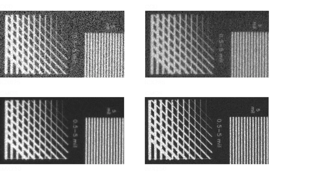
Read noise
Modern CMOS sensors go down to a read noise of only 2 e¯/pixel. Read noise (or temporal dark noise) is the noise added to a signal per shutter event and is given in e¯/pixel.
Dark current & fixed-pattern noise
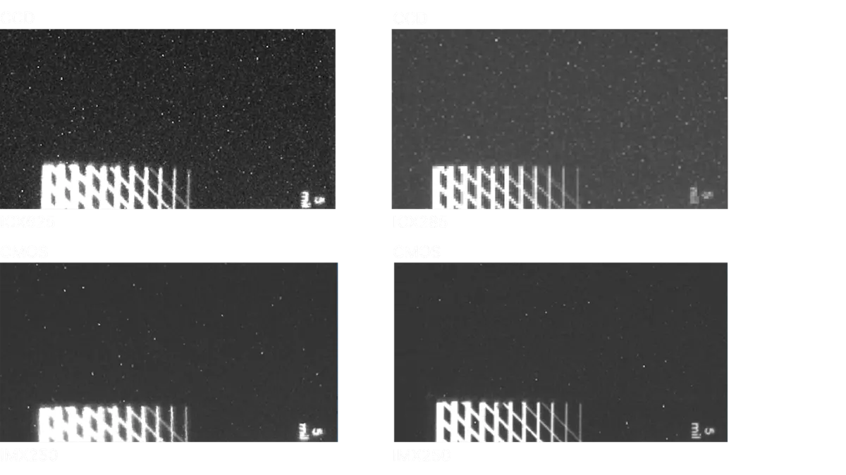
Dark current, another noise source that is relevant for fluorescence applications, becomes important when exposure times increase. This occurs when electrons leak during exposure and is expressed in e¯/pixel/s. As a rule of thumb, the dark current doubles with each temperature increase of 7 °C.
Noise types that describe not a temporal- but a space-related behavior are called fixed-pattern noise; this describes deviations that can be seen between different pixels. It can be caused by pixel electronics or by inconsistent temperatures over the sensor area.
Standardized quantification measures of these noise types are the DSNU (dark signal nonuniformity), which describes the deviation of generated electrons without any light signal, and the PRNU (photoresponse nonuniformity), describing the pixel-to-pixel deviation at a certain light level. By setting cutoff values on pixel-to-pixel deviations, one can further differentiate and describe outlying pixels as defect pixels, such as hot pixels, that show high gray values without a corresponding signal. Certain camera manufacturers already correct defective pixels during quality control by interpolation of neighboring pixels, so integrators are not impaired by these artifacts.
Choosing the right interface for your fluorescence-based application
To decide which interface is required, the following points should be considered based on the application: data/image rate, cable length, standardization, integration effort, and costs. The current state-of-the-art interfaces for integration into fluorescence microscopy-based systems include:
USB 3.2 Gen 1 (former USB 3.0): Established plug-and-play interface with the simplest integration. Allows data rates of approximately 380 MB/s (meaning e.g. 75 fps at 5 MP). Cable lengths up to several meters (including power supply) and multi-integration are supported.
GigE Vision: Used when longer cables and a more precise synchronization of multiple cameras are required. The bandwidth of classic GigE is around 100 MB/s.
5GigE Vision: Around five times faster than the GigE. It is already integrated into the ace 2 series.
Other Interfaces: USB 3.2 Gen 2 & 10GigE: USB 3.2 Gen 2 offers approximately twice the bandwidth of Gen 1 but has slightly shorter cable lengths. It is increasingly being used in practice. 10GigE doubles the 5GigE bandwidth, achieving ten times the transmission speed of classic GigE.
Vision standards are available for all mentioned interfaces and provide specifications developed by leading camera manufacturers to improve the design, effort, and performance of vision systems for camera integrators.
When cooling systems are needed in fluorescence imaging
The temperature of the sensor has a central influence on the dark current, which worsens the SNR and image quality, especially when the light signals are weak and longer exposure times are needed. This means that cooling the cameras can be important, but it is not always necessary in fluorescence imaging.
Since cooling measures significantly impact the system costs, most cameras aren’t actively cooled, which is already sufficient for applications with good fluorescence signals. But even in these cameras, the design influences the sensor temperature:
Heat generation should be avoided by operating the camera with low power consumption.
Additionally, the heat should be efficiently transported to the outside via the internal hardware design and by mounting the camera on another heat-dissipating carrier.
Thermoelectric (Peltier) elements are used to actively cool a sensor, and usually an integrated fan dissipates the heat generated by the Peltier element to the outside. The fan also helps prevent condensation moisture when temperatures fall below the ambient temperature. If it is necessary to prevent vibrations (which can be caused by the fan) in the system, some cameras can even be water-cooled.
How to improve image quality through firmware features
Beyond the hardware and sensor specifications, the cameras can offer firmware features that improve image quality in low-light conditions. One example is the defect pixel correction:
The manufacturer operates the camera at different exposure times during the final inspection, and defective pixels are located and stored in the camera’s cache. In operating mode, the values of the defective pixels are interpolated by the weighted sum of the neighboring pixels, improving image quality and SNR.
The current CMOS sensor generations enable applications that were not previously possible without investing several thousand euros in a CCD camera. The importance of these new possibilities continues to rise, since fluorescence is becoming an increasingly used tool in life sciences to visualize structures and processes.
Fluorescence applications using Basler vision technology
Fluorescence is a physical phenomenon and not just a specific technology. The possible methods – e.g., for analytics, quantitative determinations, or visualizations used in the life sciences – are almost infinite. Fluorophores can be coupled to various carriers such as proteins (often antibodies), nucleic acids, or microparticles. But they can also be integrated as gene technology markers in organisms to examine cell-biological functions and processes.
Aside from the life sciences, fluorescence-based methods are also used in other areas, such as:
Material analysis
Forensics
In-vitro diagnostics
Point-of-care systems
Surgical microscopy
Immunofluorescence microscopy
Pharmaceutical research
In the in-vitro diagnosis of autoimmune or infectious diseases, the technology of indirect immunofluorescence microscopy can be used to detect specific antibodies in the patient’s blood.
In addition to manual microscopy, there are already automated systems that give lab physicians suggested findings based on fluorescence patterns of the cells incubated with patient serums, as evaluated by software. Another system, in turn, analyzes patient serums for malaria pathogens in less than 3 minutes. The analysis is performed with vision-based algorithms that also take fluorescence signals into consideration.
Point-of-care systems are increasingly gaining significance in medical diagnostics. Among other things, they make it possible to establish better medical care even in economically and infrastructurally weak regions. Lab-on-a-chip technologies enable the processing of patient samples on a small chip, without requiring complex lab equipment.
In surgical microscopy, surgeons are increasingly supported by specific fluorescent markings of blood vessels or tumor tissue, enabling them to operate with perfect precision using fluorescence-guided surgery. Dentists can also offer faster and more specific treatment, for example, by selectively visualizing tooth areas affected by caries during treatment. Fluorescence-microscope applications are also used in pathology to examine tissues from patient biopsies for possible diseases.
Life sciences offer a broad range of fluorescence-based applications in which microscopic examinations have a significant share. Immunofluorescence microscopy enables the specific detection of proteins. For example, it supports detecting the localization in cells and tissues or as markers for beginning cell death, depending on test conditions. Nowadays, live cell imaging can also be performed for longer time periods on automatic systems.
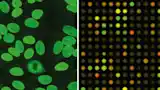
Miniaturization and parallelization to increase analysis numbers are especially significant in pharmaceutical research, since a very high number of samples are screened analytically in the search for new active substances. This is where microarrays and high-content screening systems are used.
With automatic colony counters, fluorescence markers can be used in Petri dishes to select successfully transfected cells to subsequently pick a sample of the respective colony. This means it verifies whether specific genetic material was transferred to the cell as part of an experiment, and the researchers can continue using this for their research.