Process- and Quality-Optimized Foil Manufacturing
Classify and analyze error images with high detection rates
- Customer
- R.A.M. Ltd.
- Location
- Germany
- Date
- 2018
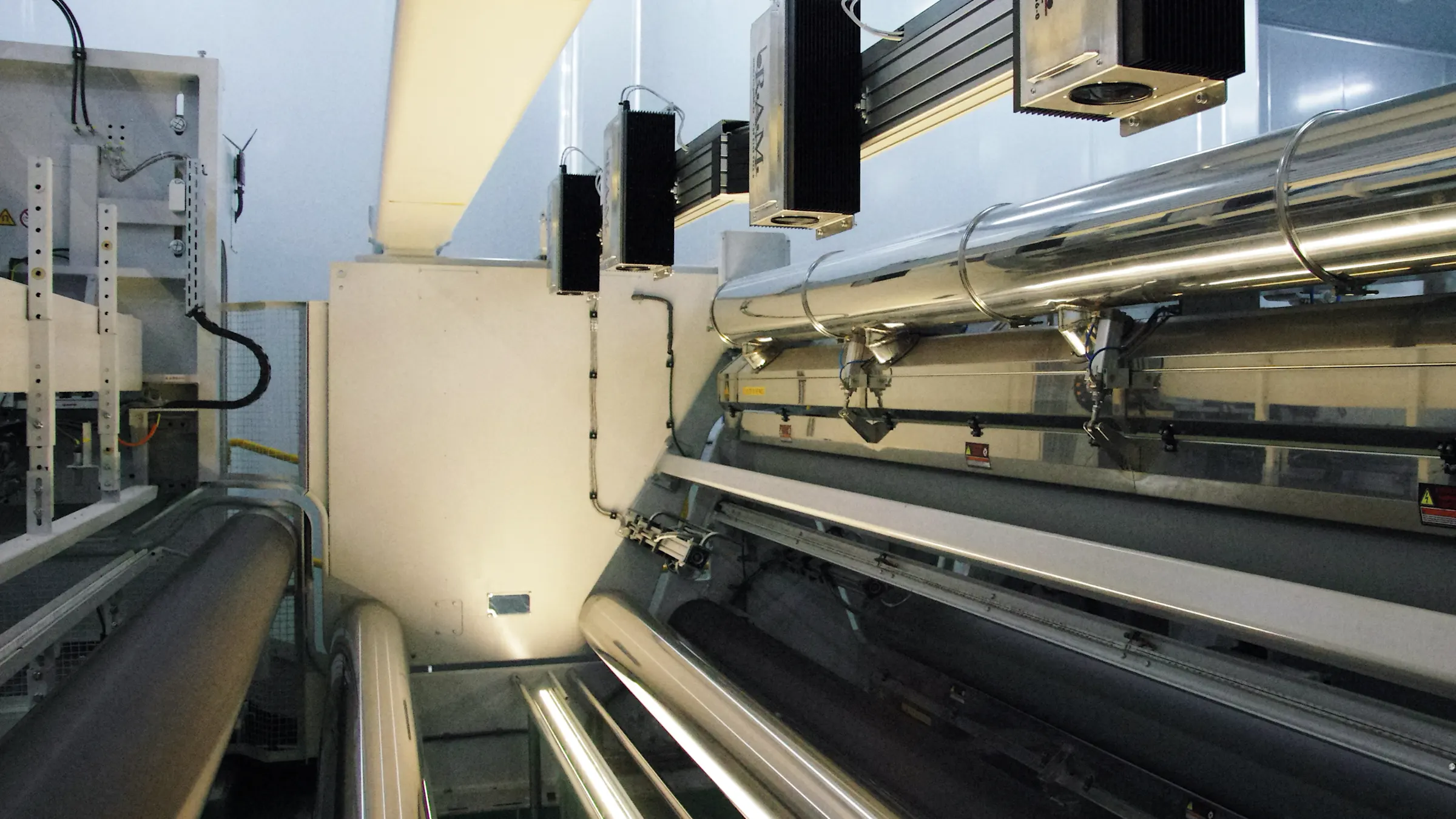
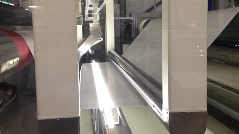
In the production of band material such as foils, it is important to deliver flawless quality to the end customer to avoid returns and expensive reworking. The inspection system from R.A.M. GmbH (with integrated frame grabbers) enables the foils to be reliably inspected across the entire surface with high resolution. The system can be used to reliably and promptly differentiate between detected defects - and thus initiate quality assurance measures in good time.


How does the inspection system work?
As soon as a system is ready for foil manufacturing, the matching line scan cameras go into operation. The high-resolution CoaXPress gray cameras with 8-bit image depth evaluate 256 different gray values as threshold values for each pixel of the moving band material. If the pixel tolerance range of very high (= lighter) to very low (= darker) values (i.e. the respective threshold value) is exceeded, the area on the foil is considered defective. When detecting defects, the camera only transmits the affected defect area instead of the entire line image for a detailed and resource-saving evaluation.
To find defects on and in belt material, the inspection system scans the entire front and back of the film at possible web widths of 50 mm to 10 m. This is done, for example, with a camera resolution of 81,920 pixels in CD (Cross Direction) by connecting five 16k cameras in parallel, which can be expanded. The system easily achieves a scanning rate of 40,000 lines per second. Fluorescence and LED line lights are available as illumination sources for transmitted light, bright field, dark field, or incident light.

Frame grabber for high speed and resolution
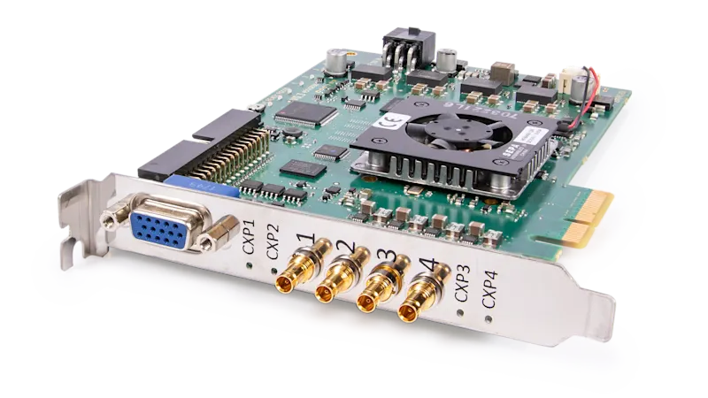
The previously used 2k cameras could hardly meet the high requirements for speed, resolution, and image quality and were replaced by up to 16k CMOS line scan cameras with an integrated frame grabber. These cameras allow image pre-processing on the frame grabber's FPGA processor.
Even very small defects can be detected with a single 8k camera, which is sufficient to find the usual defect sizes of 0.2 mm without gaps in the foil material. For even higher requirements, it is also possible to set up a parallel connection of several 4k, 8k, or 16k cameras with frame grabbers via Ethernet.
Software solution using VisualApplets
The FPGA processor on the frame grabber can be individually programmed for special image processing applications using the graphical development environment VisualApplets. For example, the recorded pixels are sorted in the correct order using a sensor correction. Another application counts and classifies the detected errors.
Optical faults are automatically classified according to fault classes, such as specks/gels, burn marks, fish eyes, impurities, inclusions, or flies, and displayed continuously as images as well as in symbolic and graphic form. Gray value images of these defects (defect section display) are available for further evaluation.
The cooperation with the supplier leads to higher quality in foil manufacturing. Defects on foils can now be detected, classified, and promptly evaluated at high speed with the desired high resolution and within a certain tolerance range.
Helpful vision system features
Very short camera exposure time of 25 µs allows high line speeds for higher data throughput
Independent programming of specific image processing applications on the frame grabber FPGA with VisualApplets
Pre-analysis of the data in the FPGA without an additional computer reduces the amount of data on the frame grabbers for higher performance
Software changes can be carried out independently and updates for the camera system can be provided promptly
Little training required for programming with VisualApplets if previous knowledge is available
Products for this solution
Looking to implement a comparable solution? These products will help you.
