Basler Vision Simulation
How to develop a vision system in simulation
We will show you step by step how to select and configure suitable cameras and lenses. Since homogeneous scene illumination is particularly important for reliable results, lighting products receive their own section.
User interface
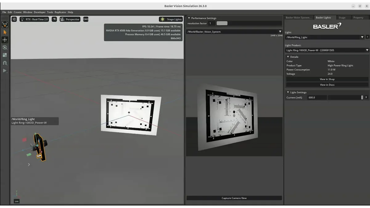
The user interface consists of the following:
The viewport on the left shows the simulated scene as if you were standing next to the setup.
The middle viewport shows the view through the Basler camera.
On the right, there are different setting panes for configuring the vision system and the simulated scene.
Loading a sample scene
Go to the menu bar and select "File"
Select "New From Stage Template"
Choose one of the three sample scenes:
This example shows a setup for the optical inspection of a PCB. The setup includes two camera–lens combinations, two bar lights, and a ring light. The second camera–lens combination is mounted at the center of the ring light.
The scene name is “Basler Multi Camera PCB”.This example includes two camera–lens combinations, a bar light, and a test chart.The camera-lens combinations are positioned at two different distances in front of the test chart. This configuration allows for the evaluation and adjustment of sharpness from different positions.
The scene name is "Basler Multi Camera Focus Bar Light".This example includes a camera, a lens, a ring light, and a test chart. The camera–lens combination is mounted at the center of the ring light. A test chart is included to evaluate and adjust sharpness.
The scene name is "Basler Test Chart And Ring Light".
Default camera and lens
Go to the settings pane "Basler Vision System".
Click the small [+] button to add vision products.
The camera model a2a2448-75ucPRO and the lens model C125-0818-5M f8mm are added by default.
Moving the camera–lens setup
Go to the left viewport.
Select "Move" tool.
You can move the camera–lens combination using the transform gizmo. A gizmo is an interactive control element in 3D software that allows you to move, rotate, or scale objects directly in the viewport.
The axes are color-coded as follows: X = red, Y = green, Z = blue.
Click on the red, green, or blue arrow to move the object along the corresponding axis (X, Y, or Z). to move the object along the corresponding axis (X, Y, or Z).
Use the colored squares to move the object within a plane:
Blue square: move along the X-axis plane
Red square: move along the Z-axis plane
Green square: move along the Y-axis plane
To move the object freely in all three dimensions, click and drag the center dot.
This allows precise positioning of your camera–lens setup within the scene.
Rotating the camera-lens setup
Go to the left viewport.
Choose the Rotate Tool from the left Toolbar.
Use the rotation gizmo: A rotation gizmo will appear with three colored circles:
Red: rotation around the X-axis
Green: rotation around the Y-axis
Blue: rotation around the Z-axis
Rotate the object: Click and drag one of the colored circles to rotate the object around the corresponding axis.
Free rotation (optional): Dragging outside the circles allows more freeform rotation depending on the view.
Tip:
For precise adjustments, you can also enter exact rotation values in the Properties panel.
Automatically position the camera-lens setup and set focus distance
Select the object and camera–lens setup: Click on the object you want to focus on and the camera–lens setup using the Select Tool
Open the Lens Settings Panel
Automatically position the camera
Click the “Look at selected object” button to automatically position the camera–lens setup so it points directly at the selected object.
Automatically set focus distance
Click the “Set focus to selected object” button to automatically adjust the camera’s focus to the selected object.
Tip
Always first use the “Look at selected object” button for a precise alignment of camera-lens to object. Then use the “Set focus to selected object” button.
You can repeat this process whenever you move objects or want to quickly reframe your scene.
Load costum CAD files
To import standard CAD data and convert native CAD formats to USD or UDSA files, the NVIDIA Omniverse CAD Converter is used. These files are optimised for real-time rendering and collaboration.
Prerequisites
Activated CAD Converter-extension. When using the FAT package, it's enabled by default.
Supported CAD file extensions
The CAD Converter supports a range of CAD formats. This includes:
Common CAD exchange file formats like JT, STEP, IGES, OBJ, FBX
File formats of CAD software like Autodesk Inventor, SolidWorks, Creo Pro/E, CATIA, NX
For a detailed list of supported CAD files, see NVIDIA Omniverse User Manual | Supported CAD file formats
Method 1: Import directly into the stage
Open your Omniverse app and load or create a USD stage.
A basler sample scene should be loaded by default. If not, it's possible to choose an exisiting sample USD stage by clicking Basler --> Sample Scenes.
Go to File --> Import.
Choose Import to Stage if prompted.
Browse to your CAD file (for example *.sldasm, *.jt, *.step) and confirm.
The imported model appears in the Stage tree.
Method 2: Convert to USD from the content browser
Open Window --> Content to show the Content Browser.
Navigate to the folder that contains your CAD files.
Right‑click the CAD file and choose "Convert to USD".
Typical converter options
The CAD Converter usually offers options that affect how geometry and scene structure are generated. It looks like this:
Note: The supported options depend on the CAD converter that is used.
For more advanced controls, check the CAD converter extension documentation: NVIDIA Omniverse User Manual | Converter Options.