Magnification, Numerical Aperture (NA) and Resolution in Microscopic Imaging
In microscopic imaging, engineers often confuse magnification with resolution, mistakenly assuming that increasing magnification automatically reveals finer details. This misconception leads to inefficient system setups and missed features in critical applications like semiconductor inspection, biomedical imaging, and precision metrology. This article clarifies the relationships between magnification, numerical aperture (NA), and resolution, and guide vision engineers in designing high-performance vision systems at micron and sub-micron scales.
Magnification in microscopic imaging
At its core, microscopic imaging relies on magnification to produce an enlarged view of the sample. There are two types: optical magnification and digital magnification. However, because digital magnification (which uses interpolation) enlarges images without adding new detail and is unsuitable for precision inspection, this article will focus on optical magnification.
Optical magnification
Optical magnification physically enlarges the image before it reaches the sensor. This happens through the combined effect of the objective lens and the tube lens. When calculating system magnification, you can take one of the following two approaches depending on your setup—either standard manufacturer objectives or custom lens assemblies.
A. Using manufacturer specifications (standard systems)
In most industrial and research microscopes that use infinity-corrected optics, objective lenses are labeled with a nominal magnification (e.g., 10×, 20×, 50×). This magnification assumes the use of a standard tube lens focal length — typically 200 mm, though some manufacturers use 180 mm or 165 mm.


B. Using focal lengths directly (custom or OEM optics)
In many OEM or custom vision systems (e.g., machine vision), engineers often bypass manufacturer magnification values and calculate magnification using fundamental lens optics:
Msystem=ftube lens / fobjective
Where:
ftube lens: Focal length of the tube lens or relay lens
fobjective: Focal length of the objective lens
This method provides flexibility when integrating custom optics or designing compact systems without standardized components.
Example:
A 200 mm tube lens with a 20 mm objective gives: M = 200 / 20 = 10×
A 100 mm tube lens instead yields: M = 100 / 20 = 5×.
Tube lenses or adapters are often labeled 0.5×, 1×, 2×, etc., which corresponds to how they scale the final image based on the above ratio.
When building a vision system, use manufacturer-based formulas for standard setups and focal length ratios for custom designs—especially in OEM and machine vision contexts. Both methods are accurate when used consistently. The key is selecting the model that aligns best with your system’s integration and performance goals.

Important design considerations:
Higher effective magnification reduces the field of view (FoV), potentially requiring more image stitching for large-area inspections.
Increasing magnification without increasing NA does not improve resolution; it just spreads the same resolution over more pixels (oversampling).
System design should align with the Nyquist sampling criterion—at least 2 pixels per smallest resolvable feature are needed to avoid aliasing.
However, this requirement depends on the application:
If the goal is to detect particles (e.g., presence/absence), a 1 µm/pixel resolution may suffice.
If the objective is to inspect shapes, edges, or fine patterns, then Nyquist sampling becomes essential to accurately resolve detail and avoid information loss.
Example:
To image 1 µm features with a 5 MP camera (3.45 µm pixel size), you need at least:
3.45 µm / 1 µm = 3.45 => Need at least 6.9x magnification
This ensures each 1 µm feature spans at least 6.9 µm on the sensor—satisfying the 2-pixel rule.
Resolution and numerical aperture (NA)
While magnification controls how large a feature appears on the sensor, it is the numerical aperture (NA) that governs the system’s ability to resolve fine details. This section explores how NA influences resolution, and how it can be optimized for different imaging scenarios.

What is NA?
Numerical Aperture (NA) measures the lens’s ability to gather light and resolve fine detail. It directly impacts resolution, image sharpness, and brightness. The greater the value of NA, the greater the resolution of the result image. NA can be calculated as:
NA = n ∙ sin 𝜽
Where:
n: Refractive index of the medium between the objective lens and the sample. (air = 1.0, oil = ~1.5)
𝜽: Half-angle of light cone collected by the lens
NA increases when:
Using a medium with a higher refractive index (n) than air (e.g., immersion oil or water).
Increasing the aperture diameter.
Reducing working distance, allowing steeper light angles into the lens.

Resolution as a function of NA
Optical resolution is limited by diffraction:
Resolution=0.61⋅λ/ NA = 0.61⋅λ/ (n ∙ sin 𝜽)
Where:
λ: the illumination wavelength
A higher NA enables the resolution of smaller features— a critical factor in applications such as wafer inspection or metrology, where edge sharpness and fine pattern distinction are required.
However, optical resolution improvements only translate to usable image detail when the sensor’s pixel size and magnification meet the system’s resolving power (Nyquist sampling must be satisfied).
Note: This resolution formula originates from diffraction theory and the Rayleigh criterion, which models how light forms patterns like the Airy disk. These concepts will be covered in an upcoming advanced article on optical diffraction and imaging limits.

Does increasing NA solve everything?
Not entirely. While NA improves resolution and brightness, it comes with trade-offs:
Shorter working distances, limiting accessibility.
Shallower depth of field.
Requires more precise alignment and focus.
Higher NA lenses are often more sensitive to aberrations and more expensive.
In addition, NA interacts with image-side optics (explained next), impacting contrast and overall system fidelity.
Object-side vs. image-side numerical aperture
A complete imaging system includes both object-side and image-side numerical apertures, each affecting different image qualities.

Definitions and equations
There are two kinds of NAs:
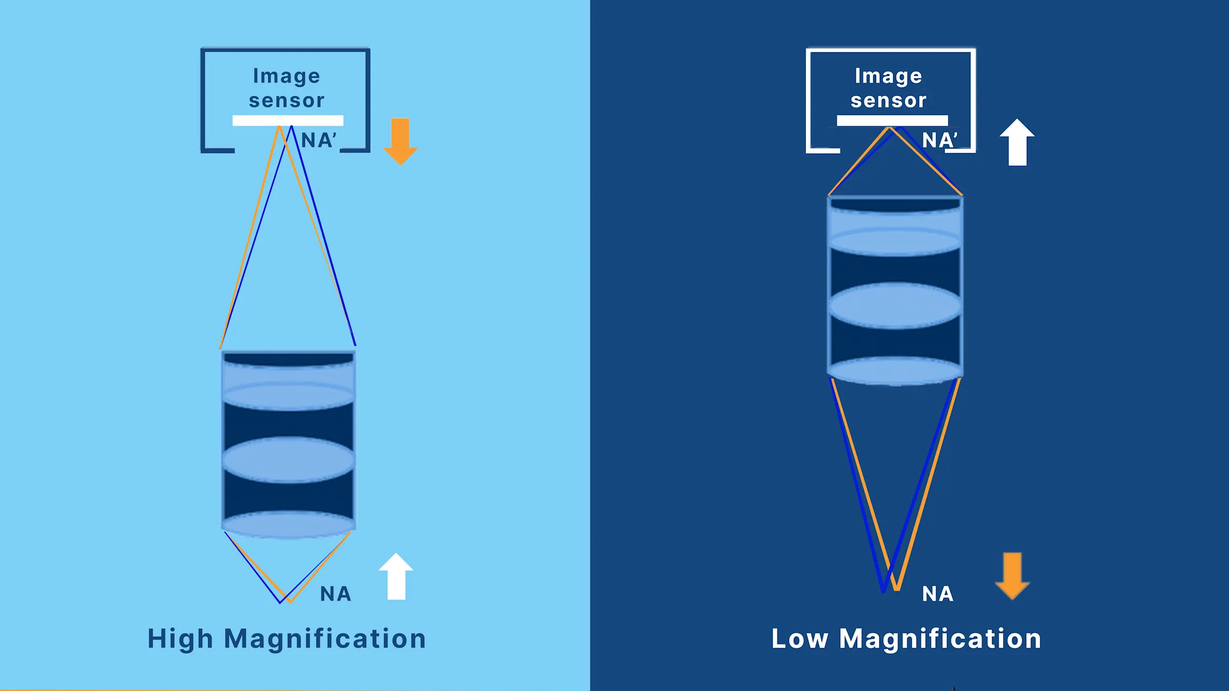
Object-side NA (NA): Between the sample and the objective lens
Image-side NA (NA′): Between the tube lens and the image sensor
These two NAs are related by the following equation:
NA = β X NA'
Where:
β: represents lateral magnification, defined as image size divided by object size.
This means that as magnification increases, the object-side NA increases while the image-side NA decreases. In practice, higher magnification is often used to achieve a larger NA for resolving smaller defects. However, this also reduces the image-side NA, which can lead to darker and blurrier images.

The trade-off between NA and NA′
This inverse relationship is critical for system design:
NA controls how small a feature can be resolved.
NA′ governs how clearly that feature is transferred to the sensor — i.e., contrast, particularly at high spatial frequencies.
NA′ is tied to the Modulation Transfer Function (MTF) — a measure of contrast across feature sizes. If NA′ is too low:
The MTF declines rapidly at high frequencies.
Fine details become poorly visible or even invisible, despite being technically resolved.
In a word, high NA without sufficient NA′ can produce images that are sharp but lack the contrast necessary for reliable inspection or measurement.
Summary
In microscopic imaging, magnification, NA, and resolution must work together. Optimizing just one won't guarantee better image quality.
Magnification controls how big a feature appears on the sensor. It needs to match the camera’s pixel size to avoid oversampling or undersampling.
NA (Numerical Aperture) determines how small a feature the lens can resolve. Higher NA improves detail and brightness but reduces depth of field.
NA′ (Image-side NA) affects how clearly details are transferred to the sensor. It influences contrast and visibility, especially at high spatial frequencies.
Key takeaway:
High magnification needs high NA for resolution — and both need enough NA′ to maintain contrast. A well-balanced system considers resolution, contrast, and field of view together.
Further reading:
For a detailed exploration of physical and system-level limits, including the Abbe diffraction limit, Rayleigh criterion, optical aberration and Nyquist sampling requirements, continue to "What Really Limits Microscopy Resolution".
To the Article: What Really Limits Microscopy Resolution