Time-of-Flight versus Stereo Vision - Who Scores Where?
Compared with 2D methods, 3D image processing provides machine vision users with additional insights. This third dimension has benefitted numerous industries—especially factory automation, robotics, logistics, and medicine—by providing further vision technologies and applications. Two 3D methods in particular have become well established: Time-of-Flight (ToF) and stereo vision, which are examined in more detail and compared here.
Applications des caméras Time-of-Flight
Dans notre livre blanc, nous répondons aux questions suivantes :
Quelle est la différence entre les différentes technologies 3D ?
Comment fonctionne exactement la technologie du Time-of-Flight?
Comment les caméras ToF peuvent-elles être utilisées dans la logistique, la robotique et la médecine ?
3D vision provides the spatial dimension
With 2D image processing, the captured image is necessarily always a two-dimensional projection of a three-dimensional object. Depth information cannot be captured with a 2D camera. Depending on the viewing angle, this can result in a different contour of a three-dimensional object in the image. That said, this shape and depth information is not relevant for many two-dimensional applications. More commonly, 2D imaging is used for structure and color analysis, part identification, presence checks, damage or anomaly detection, character recognition, and dimensional accuracy inspection. A prerequisite for these tasks is optimal lighting that produces sufficient contrast in the image.
On the other hand, with 3D images the height information of a scene is also available. This means volumes, shapes, distances, positions in space, and object orientations can be determined, or a spatially dependent presence check of objects can be performed. As with 2D imaging (and depending on the technology), there are prerequisites such as lighting conditions or surface properties that must be considered for optimal image acquisition.
2D versus 3D vision technology
Requirements for the Task | To the cameras with 2D sensor | 3D |
|---|---|---|
Analysis of volumes and/or forms | + | - |
Structure and color must be recognized | + | - |
Good contrast information available | + | - |
Contrast information is poor or non-existent | - | + |
Height differences must be recognized | - | + |
Positioning task / detection in the third dimension | - | + |
Barcode and character recognition | + | - |
Component identification | + | + |
Checking the presence of components | + | + |
Damage detection | + | + |
Comparing 3D technologies
What are the characteristics of time-of-flight and stereo vision, what are their special features and what are their strengths and weaknesses?
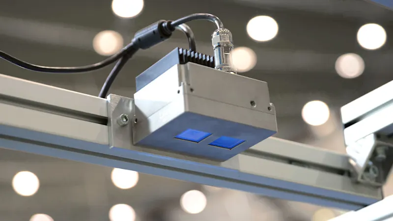
Time-of-Flight
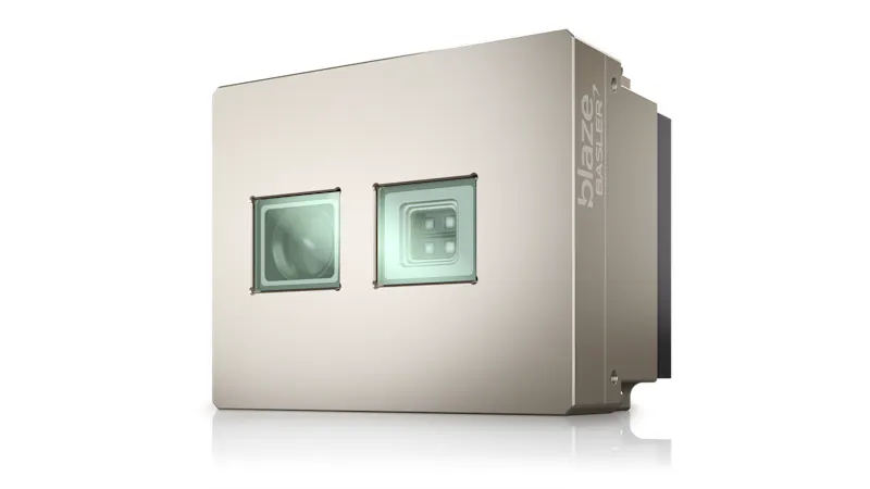
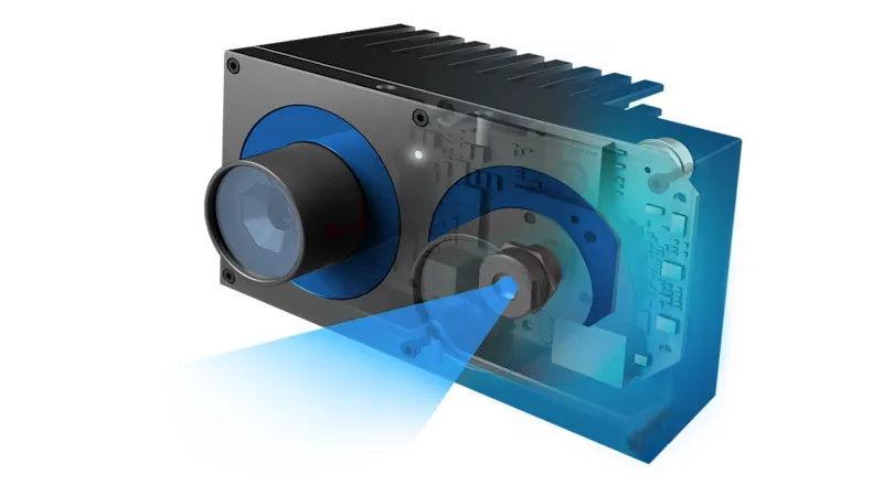
Time-of-Flight is a very efficient technology that measures distances to obtain depth data. For this purpose, a light source integrated in the camera emits light pulses that hit the object. The object reflects the light pulses back to the camera. Using the time required for this, the distance and thus the depth value can be determined for each individual pixel. As a result, the 3D values for the inspected object are output as a spatial image in the form of a range map or point cloud. The ToF method also provides a 2D intensity image in the form of gray values for each pixel and a confidence image that represents the degree of confidence in the individual values.
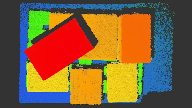
ToF does not require contrast or specific features such as corners and edges for 3D capture. The capture can also be performed almost independently of the intensity and color of the object, making it easy to separate the object from the background using image processing. ToF also works with moving objects and can perform up to nine million distance measurements per second with millimeter accuracy. Compared to other 3D cameras, ToF cameras are less expensive, very compact, and less complex. This allows for easy installation and integration.
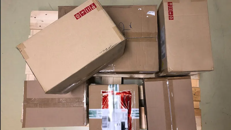
However, the camera only delivers the best results under certain environmental conditions and for a defined measuring range. Due to the underlying time-of-flight measurement method, multiple reflections of the emitted light, for example through corners or a concave shape of the measurement object, lead to deviations in the measurement results with the ToF method. Highly reflective surfaces too close to the camera can cause flare in the lens, resulting in artifacts. With very dark surfaces, there is a risk that too little light is reflected for a robust measurement. A working distance that is too small can also restrict the method, which means that ToF is suitable overall for medium measurement or depth accuracy.
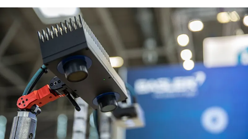
Stereo vision
Stereo vision works similar to a pair of human eyes. Depth information is obtained through synchronous images taken by two 2D cameras from different viewing angles. 3D data is then calculated based on extrinsic parameters (the position of the two cameras relative to each other) and intrinsic parameters (such as the optical center and focal length of the lens for each camera). Together, these result in camera-specific calibration values. To calculate the depth information, the two 2D images are first rectified. Then a matching algorithm searches for the corresponding pixels in the right and left images. With the help of the calibration values, a depth image of the scene or object can be generated as a point cloud. The best working distance for this procedure depends on the distance and setting angle of the two cameras and therefore varies.
Compared to ToF, this method does not require an active lighting unit such as light or laser beams. However, it always requires a minimum amount of ambient light, since technically these are two separate 2D cameras. If conditions are difficult for other 3D methods with an active lighting unit, stereo vision can provide better results. Examples include bright ambient light, overlapping measurement areas, and reflective surfaces.
In the case of surfaces with little structure, the stereo vision method finds too few corresponding features in both images to calculate three-dimensional information from them. These limitations can be overcome by artificially generated surface structures using light. A light projector that projects a random pattern can also be integrated for this purpose.
Structured light
Rather than the dual camera setup of stereo vision, structured light replaces one of the cameras with a stripe light projector. This projects various stripe patterns with a sinusoidal intensity curve, thus creating an artificial structure on the surface that is nevertheless known to the system. The distortion of the projected stripes on the surface is used to calculate 3D information and leads to more accurate measurement results.
Sensors with structured light achieve particularly high accuracy at close range. The use of structured light generates a high computing load and is unsuitable for moving objects, since several images are acquired and processed one after the other. Therefore, this method is suitable for real-time applications only to a limited extent or at higher costs.
Advantages and disadvantages
Time-of-Flight | Stereo vision | Structured light | |
|---|---|---|---|
Range | + | o | o |
Accuracy | o | + | + |
Low-Light Performance | + | o | + |
Bright-Light Performance | + | + | - |
Homogeneous surfaces | + | - | + |
Moving objects | o | + | - |
Camera size | + | o | - |
Costs | + | o | - |
Which applications benefit
Typical applications for Time-of-Flight
Time-of-Flight is especially advantageous in applications requiring: a long working distance, a large measuring range, high speed, and low system complexity, while extreme accuracy is less relevant. Examples include:
Measuring objects (volume, shape, position, orientation)
Factory automation: find, pick, assemble objects; detect damaged objects or stacking errors
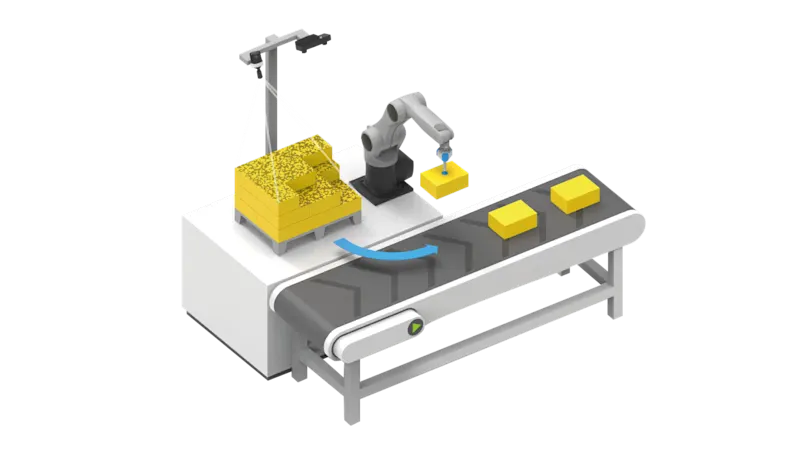
Robotics: determining gripping points for robots; gripping tasks on conveyor belts, bin picking, pick-and-place
Logistics: packaging; stacking, (de)palletizing; labeling; autonomous driving vehicles (navigation, safety warnings)
Medicine: positioning and monitoring of patients
Typical applications for stereo vision and structured light
Stereo vision already offers high measurement accuracy and is surpassed by sensors with structured light. These types of 3D sensors are suitable for detecting uncooperative surfaces with little structure or applications requiring very high measurement accuracy. Examples include:
Determining position and orientation
High-precision object measurements (volume, shape, position, orientation)
Robotics: bin picking, navigation, collision avoidance, pick-up and drop-off services
Logistics: indoor vehicle navigation, loading and unloading of machines, (de)palletizing
Outdoor: measuring and inspecting tree trunks
Component testing, e.g. damage detection
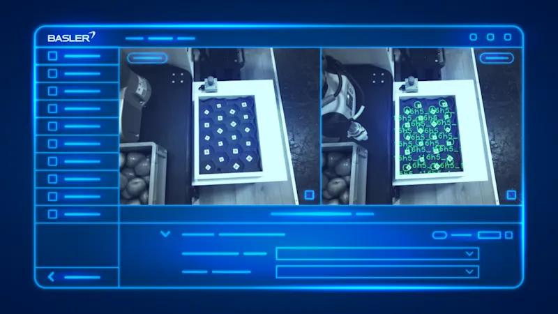
The need for 3D technology is increasing in many applications, especially when combined with artificial intelligence such as deep learning. This interaction simplifies object recognition and the precise determination of the object’s position in space. Robots are thus able to grip objects they have never seen before. Simultaneous localization and mapping (SLAM) systems use vision sensors to create high-resolution three-dimensional maps for autonomous vehicles and augmented reality applications.
Our 3D products
Find the right hardware and software for your 3D vision system here
